
INSTALLATION AND MAINTENANCE
A better experience will be achieved with the proper use of the product.
The rigidity of the base, the flatness of the installation surface and the dimensional tolerance of the shaft are inspected if they are qualified.
The tolerances recommendation for mounted shaft

| Shaft Diameter | HC,SA Series | ||||||
| Shaft tolerances recommendation (h6) | |||||||
| mm | in | μm | in | ||||
| > | ≤ | > | ≤ | max | min | max | min |
| 10 | 18 | 7/16 | 11/16 | 0 | -11 | 0 | -0.0004 |
| 18 | 30 | 3/4 | 1-1/8 | 0 | -13 | 0 | -0.0005 |
| 30 | 50 | 1-3/16 | 1-15/16 | 0 | -16 | 0 | -0.0006 |
| 50 | 80 | 2 | 3-1/8 | 0 | -19 | 0 | -0.0007 |
| 80 | 120 | 3-3/16 | 4-11/16 | 0 | -22 | 0 | -0.0009 |
| 120 | 180 | 4-3/4 | 7-1/16 | 0 | -25 | 0 | -0.0010 |
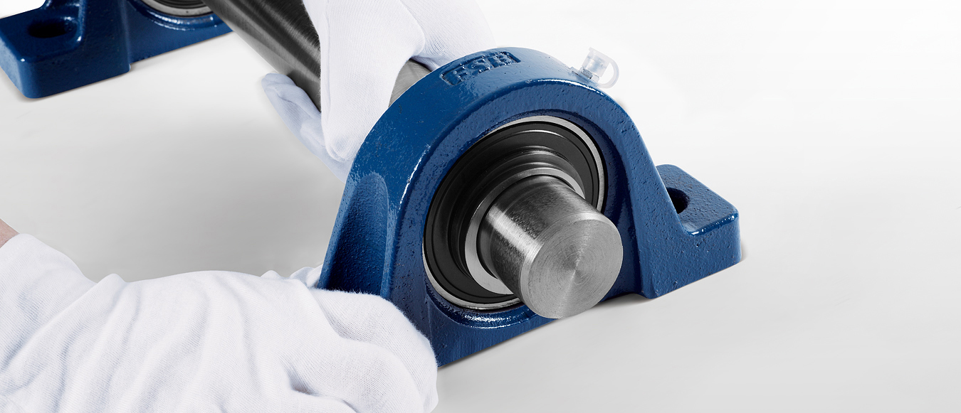
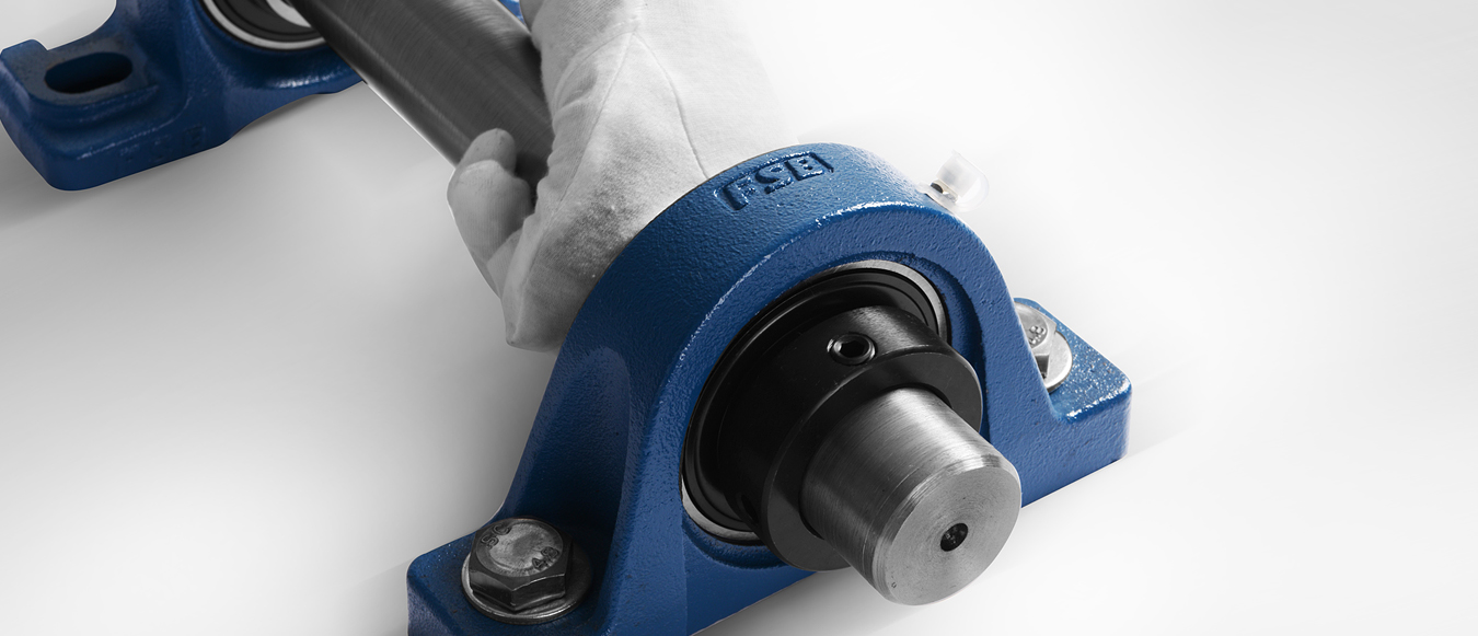
The mounted ball bearing unit is inserted into the shaft, under the fixed position.
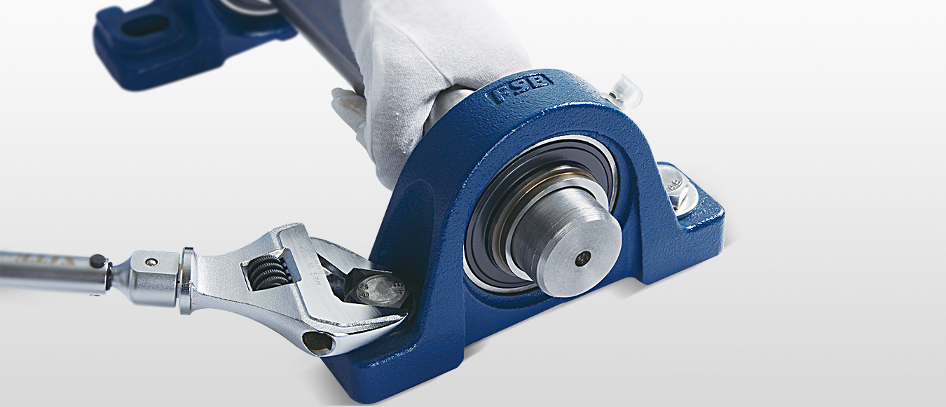
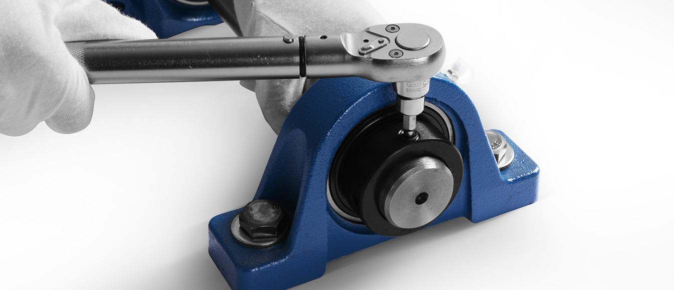
Tighten the mounting bolts of the bearing housings with the torque wrench according to the specified locking torque.
The locking torque recommendation for mounted bolts of bearing housings
| Bolt Specification | Locking torque (±10%) | |||
| mm | in | N.m | lbf.in | lbf.ft |
| M6 | 1/4 | 4.0 | 33 | 3 |
| M8 | 5/16 | 8.0 | 71 | 6 |
| M10 | 3/8 | 17 | 151 | 13 |
| M12 | 7/16 | 29 | 257 | 21 |
| M14 | 1/2 | 47 | 416 | 35 |
| M16 | 5/8 | 73 | 646 | 54 |
| M18 | - | 107 | 947 | 79 |
| M20 | 3/4 | 145 | 1280 | 107 |
| M22 | 7/8 | 200 | 1770 | 148 |
| M27 | 1 | 372 | 3290 | 275 |
| M30 | 1-1/8 | 500 | 4430 | 369 |
| M33 | 1-1/4 | 690 | 6110 | 509 |
| M36 | 1-3/8 | 880 | 7790 | 649 |
Note: apply to P, F, FS, FL, FC, FT, FA, FB, LF, FD bearing housings
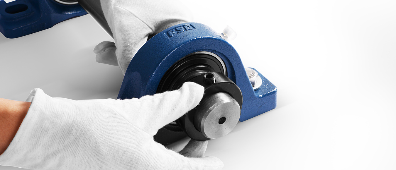
The eccentric part of the eccentric locking collar is embedded in the eccentric platform of the inner ring of bearing.
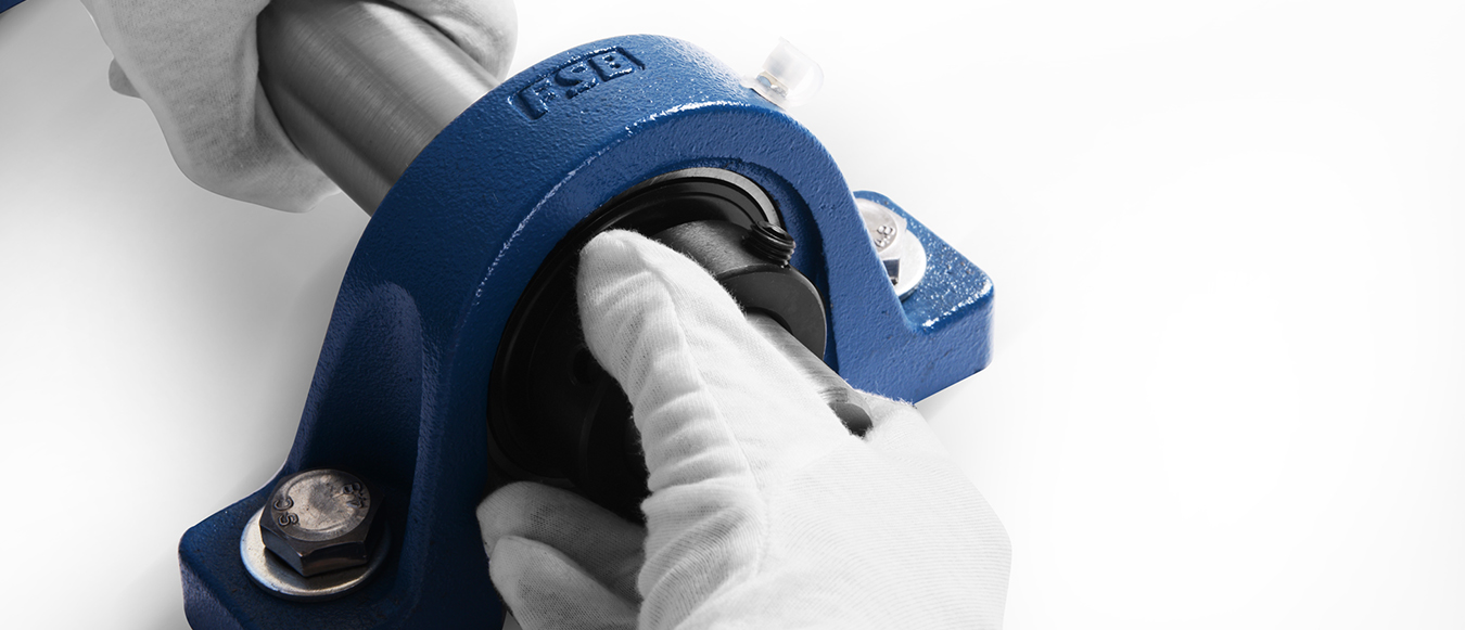
Rotate the eccentric locking collar along the shaft rotation direction to mesh with the eccentric platform of the inner ring of bearing, then use the hammer and nail gun to knock eccentric locking collar to be locked along the shaft rotation direction.
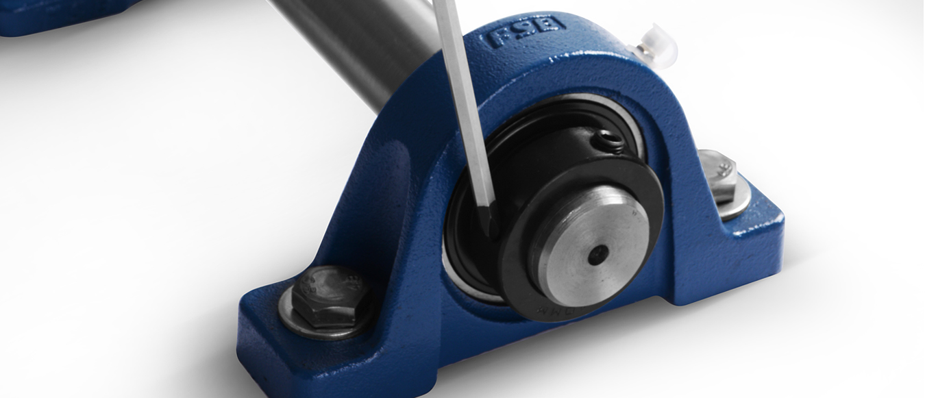
Tighten the set screws of the eccentric locking collar according to the specified locking torque.
The locking torque recommendation for set screws
| Set screw specification | Locking torque | Applicable model | |||||
mm | in | N.m | lbf.in | lbf.ft | HC200 | SA200 | HC300 |
M5×0.8 | 10-32UNF | 3.0 | 27 | 2.2 | |||
M6×1.0 | 1/4-28UNF | 4.0 | 35 | 3 | 203-205 | 201-205 | |
M8×1.0 | 5/16-24UNF | 9 | 75 | 6 | 206 | 206 | 305-307 |
M10×1.25 | 3/8-24UNF | 18 | 155 | 13 | 207-216 | 207-216 | 308-312 |
M12×1.5 | 7/16-20UNF | 28 | 248 | 21 | 211-216 | 211-212 | 313-314 |
M14×1.5 | 1/2-20UNF | 35 | 310 | 26 | |||
M16×1.5 | 5/8-18UNF | 56 | 496 | 41 | 315-317 | ||
M18×1.5 | 5/8-18UNF | 62 | 549 | 46 | |||
M20×1.5 | 3/4-16UNF | 83 | 735 | 61 | 318-320 | ||
用手转动轴,确认轴承的旋转状态是否异常。