
INSTALLATION AND MAINTENANCE
A better experience will be achieved with the proper use of the product.

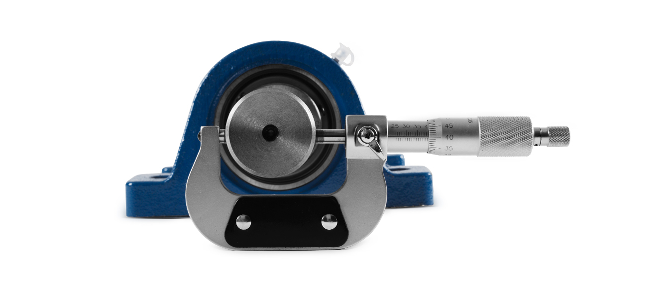
The rigidity of the base, the flatness of the installation surface and the dimensional tolerance of the shaft are inspected if they are qualified.
The tolerances recommendation for mounted shaft
| Shaft Diameter | UK Series | ||||||
| Shaft tolerances recommendation (h9) | |||||||
| mm | in | μm | in | ||||
| > | ≤ | > | ≤ | max | min | max | min |
| 10 | 18 | 7/16 | 11/16 | 0 | -43 | 0 | -0.0017 |
| 18 | 30 | 3/4 | 1-1/8 | 0 | -52 | 0 | -0.0021 |
| 30 | 50 | 1-3/16 | 1-15/16 | 0 | -62 | 0 | -0.0024 |
| 50 | 80 | 2 | 3-1/8 | 0 | -74 | 0 | -0.0029 |
| 80 | 120 | 3-3/16 | 4-11/16 | 0 | -87 | 0 | -0.0034 |
| 120 | 180 | 4-3/4 | 7-1/16 | 0 | -100 | 0 | -0.0039 |
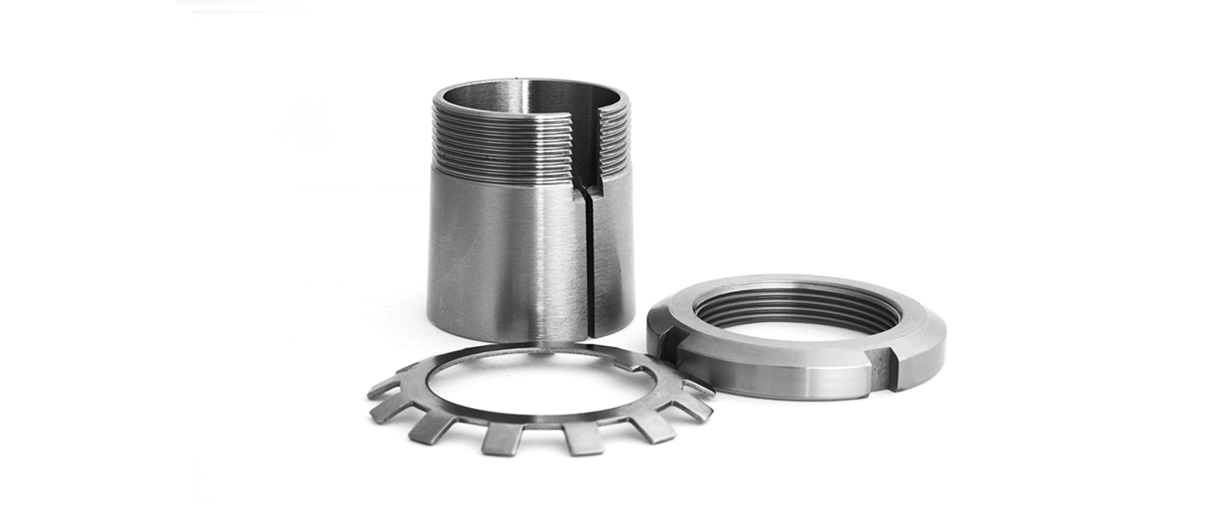
Lock nut and lock washer are splitted from adapter sleeve.
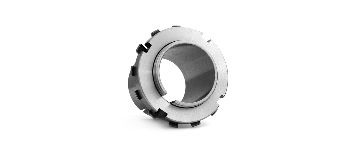
The adapter sleeve is inserted into the shaft, under the fixed installation position of mounted ball bearing units.
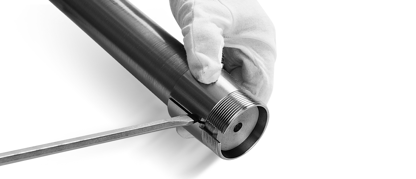
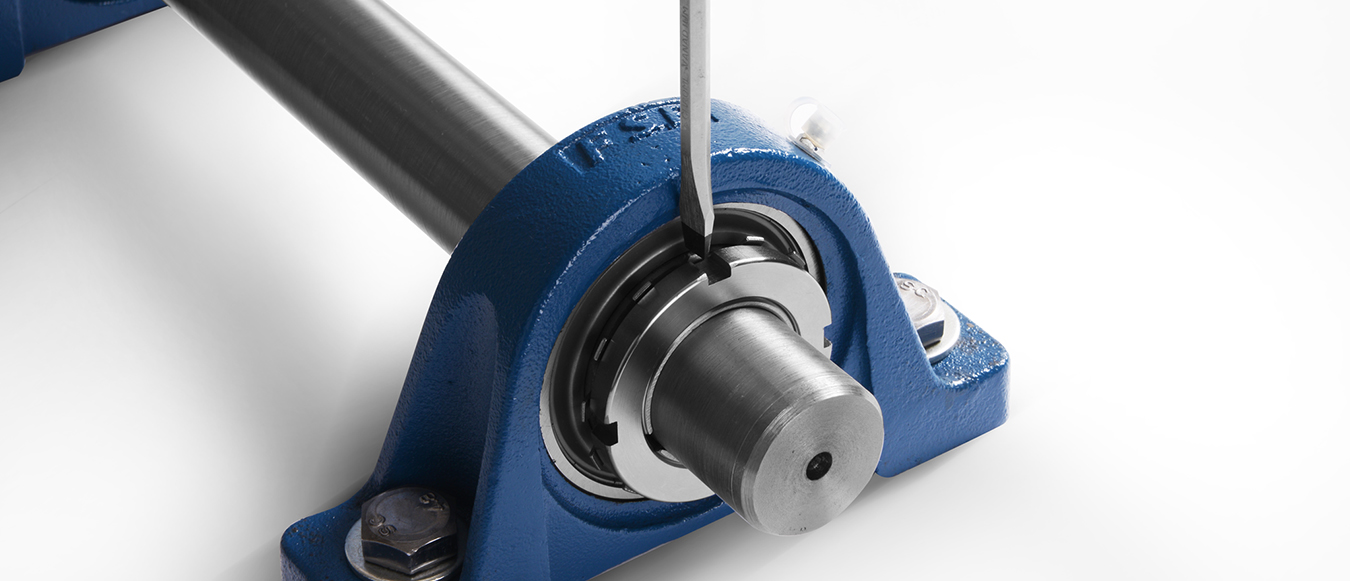
If the adapter sleeve is inserted with difficulty, the screwdriver can be inserted into the notch part of the adapter sleeve to make slot larger and easy to insert.
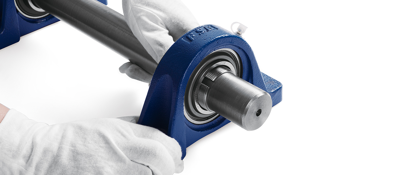
The mounted ball bearing unit is inserted into the shaft, under the fixed position.
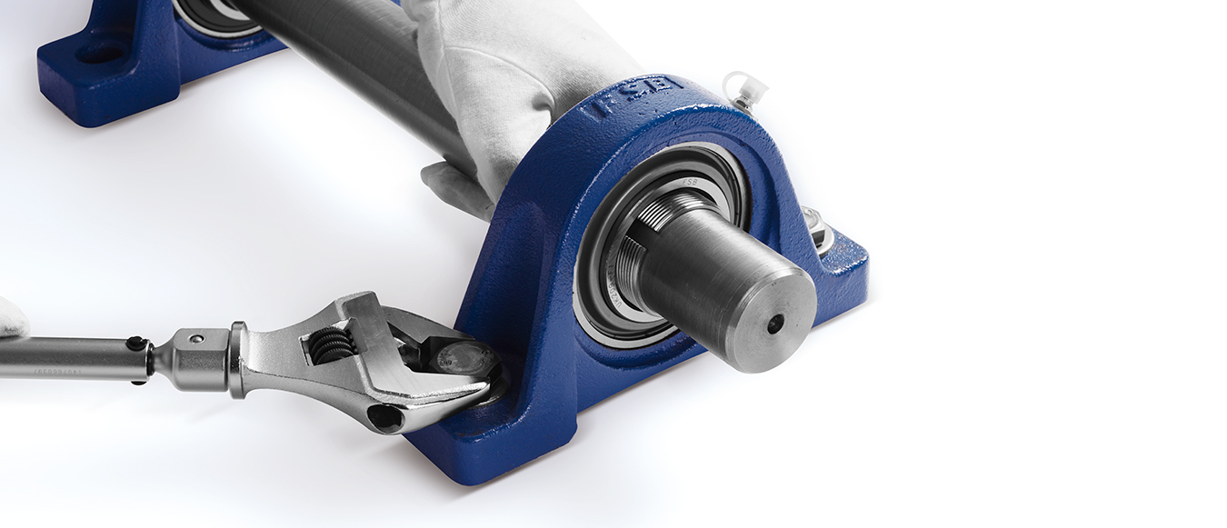
Tighten the mounting bolts of the bearing housings with the torque wrench according to the specified locking torque.
The locking torque recommendation for mounted bolts of bearing housings
| Bolt Specification | Locking torque (±10%) | |||
| mm | in | N.m | lbf.in | lbf.ft |
| M6 | 1/4 | 4.0 | 33 | 3 |
| M8 | 5/16 | 8.0 | 71 | 6 |
| M10 | 3/8 | 17 | 151 | 13 |
| M12 | 7/16 | 29 | 257 | 21 |
| M14 | 1/2 | 47 | 416 | 35 |
| M16 | 5/8 | 73 | 646 | 54 |
| M18 | - | 107 | 947 | 79 |
| M20 | 3/4 | 145 | 1280 | 107 |
| M22 | 7/8 | 200 | 1770 | 148 |
| M27 | 1 | 372 | 3290 | 275 |
| M30 | 1-1/8 | 500 | 4430 | 369 |
| M33 | 1-1/4 | 690 | 6110 | 509 |
| M36 | 1-3/8 | 880 | 7790 | 649 |
Note: apply to P, F, FS, FL, FC, FT, FA, FB, LF, FD bearing housings

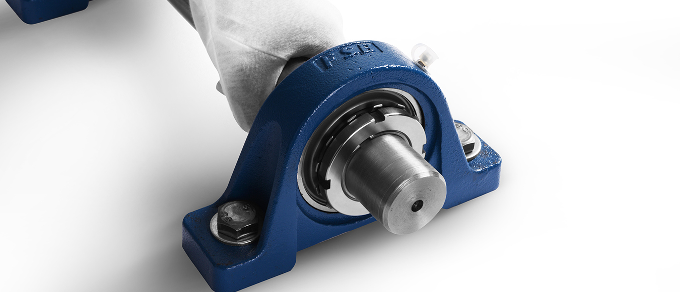
Fix the lock washer and lock nut into adapter sleeve and tighten the lock nut by hand.

Tighten the set screws of the adatper sleeve according to the specified locking torque.
The locking torque recommendation for set screws
| Bore model | Use condition: normal load (Crx0.12>Pr) | |||||||||||
| UK200 locking torque (±10%) | UKX00 locking torque (±10%) | UK300 locking torque (±10%) | ||||||||||
| N·m | lbf.in | lbf.ft | Cr(KN) | N·m | lbf.in | lbf.ft | Cr(KN) | N·m | lbf.in | lbf.ft | Cr(KN) | |
| 05 | 32 | 283 | 24 | 14 | 44 | 389 | 33 | 19.5 | 38 | 336 | 28 | 21.2 |
| 06 | 38 | 336 | 28 | 19.5 | 50 | 443 | 37 | 25.5 | 57 | 505 | 42 | 26.7 |
| 07 | 50 | 443 | 37 | 25.5 | 63 | 558 | 47 | 30.7 | 75 | 664 | 55 | 33.4 |
| 08 | 63 | 558 | 47 | 30.7 | 94 | 832 | 69 | 33.2 | 100 | 885 | 74 | 40.7 |
| 09 | 75 | 664 | 55 | 33.2 | 94 | 932 | 69 | 35.1 | 150 | 1330 | 111 | 48.9 |
| 10 | 94 | 832 | 69 | 35.1 | 138 | 1220 | 102 | 43.6 | 188 | 1660 | 139 | 62 |
| 11 | 125 | 1110 | 92 | 43.6 | 175 | 1550 | 129 | 52.7 | 225 | 1990 | 166 | 71.6 |
| 12 | 163 | 1440 | 120 | 52.7 | 207 | 1830 | 153 | 57.2 | 281 | 2490 | 207 | 81.9 |
| 13 | 188 | 1660 | 139 | 57.2 | 244 | 2160 | 180 | 66.3 | 331 | 2930 | 244 | 92.7 |
| 15 | 213 | 1890 | 157 | 66.3 | 269 | 2380 | 199 | 72.8 | 469 | 4150 | 346 | 113 |
| 16 | 250 | 2210 | 185 | 72.8 | 319 | 2820 | 235 | 83.2 | 563 | 4980 | 415 | 123 |
| 17 | 275 | 2430 | 203 | 83.2 | 369 | 3270 | 272 | 95.6 | 663 | 5870 | 489 | 133 |
| 18 | 325 | 2880 | 240 | 95.6 | 425 | 3760 | 314 | 109 | 763 | 6750 | 563 | 143 |
| 19 | - | - | - | - | - | - | - | - | 888 | 7860 | 655 | 153 |
| 20 | - | - | - | - | 613 | 5430 | 452 | 133 | 1110 | 9800 | 817 | 173 |
| 22 | - | - | - | - | - | - | - | - | 1530 | 13500 | 1130 | 205 |
| 24 | - | - | - | - | - | - | - | - | 1840 | 16300 | 1360 | 207 |
| 26 | - | - | - | - | - | - | - | - | 2210 | 20500 | 1710 | 229 |
| 28 | - | - | - | - | - | - | - | - | 2690 | 23800 | 1980 | 253 |
| Bore model | Use condition: normal load (Crx0.12 | |||||||||||
| UK200 locking torque (±10%) | UKX00 locking torque (±10%) | UK300 locking torque (±10%) | ||||||||||
| N·m | lbf.in | lbf.ft | Cr(KN) | N·m | lbf.in | lbf.ft | Cr(KN) | N·m | lbf.in | lbf.ft | Cr(KN) | |
| 05 | 56 | 496 | 41 | 14 | 79 | 699 | 58 | 19.5 | 68 | 602 | 50 | 21.2 |
| 06 | 68 | 602 | 50 | 19.5 | 90 | 767 | 66 | 25.5 | 101 | 894 | 75 | 26.7 |
| 07 | 90 | 767 | 66 | 25.5 | 113 | 1000 | 83 | 30.7 | 135 | 1200 | 100 | 33.4 |
| 08 | 113 | 1000 | 83 | 30.7 | 169 | 1500 | 125 | 33.2 | 180 | 1590 | 133 | 40.7 |
| 09 | 135 | 1200 | 100 | 33.2 | 169 | 1500 | 125 | 35.1 | 270 | 2390 | 199 | 48.9 |
| 10 | 169 | 1500 | 125 | 35.1 | 248 | 2200 | 183 | 43.6 | 338 | 2990 | 249 | 62 |
| 11 | 225 | 1990 | 166 | 43.6 | 315 | 2790 | 232 | 52.7 | 405 | 3590 | 299 | 71.6 |
| 12 | 293 | 2593 | 216 | 52.7 | 371 | 3280 | 274 | 57.2 | 506 | 4480 | 373 | 81.9 |
| 13 | 338 | 2990 | 249 | 57.2 | 439 | 3890 | 324 | 66.3 | 596 | 5280 | 440 | 92.7 |
| 15 | 383 | 3390 | 283 | 66.3 | 484 | 4280 | 357 | 72.8 | 844 | 7470 | 623 | 113 |
| 16 | 450 | 3980 | 332 | 72.8 | 574 | 5080 | 424 | 83.2 | 1010 | 8970 | 748 | 123 |
| 17 | 495 | 4380 | 365 | 83.2 | 664 | 5880 | 490 | 95.6 | 1190 | 10600 | 880 | 133 |
| 18 | 585 | 5180 | 432 | 95.6 | 765 | 6770 | 565 | 109 | 1370 | 12200 | 1010 | 143 |
| 19 | - | - | - | - | - | - | - | - | 1600 | 14100 | 1180 | 153 |
| 20 | - | - | - | - | 1103 | 9760 | 814 | 133 | 1990 | 17600 | 1470 | 173 |
| 22 | - | - | - | - | - | - | - | - | 1750 | 24300 | 2030 | 205 |
| 24 | - | - | - | - | - | - | - | - | 3310 | 29300 | 2440 | 207 |
| 26 | - | - | - | - | - | - | - | - | 3980 | 35300 | 2940 | 229 |
| 28 | - | - | - | - | - | - | - | - | 4840 | 42800 | 3570 | 253 |
| Cr= Basic Dynamic Load Rating,Pr= Equivalent Dynamic Load | ||||||||||||
The claw (1 piece) of the lock washer which is in accordance with the notch position of the outer surface of the lock nut is bent to prevent the lock nut from loosing.
Turn the shaft manually to ensure the bearing rotation bearing is normal.